-
Created by
 Stryker Ai, last updated yesterday at 06:59 pm
12 minute read
Architecture
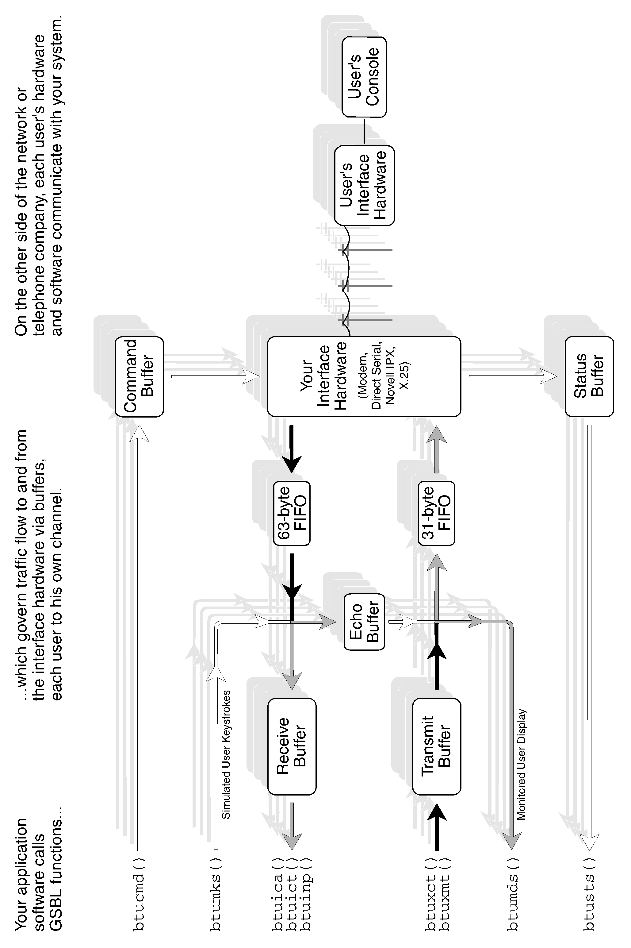
Basically, you will write software which calls GSBL functions. The GSBL will govern data traffic flow to and from the communications hardware via data buffers. Your communications hardware will then connect with users’ communications hardware. Users’ software will send requests to your software, which will provide responses.
Buffers Implemented for Each Channel
| Buffer | Access via routine | Direction of access |
| Status | btusts() | input |
| Command | btucmd() | output |
| Receiver | btuinp() / btuict() | input |
| Transmitter | btuxmt() / btuxct() | output |
| Echo | (transparent) | — |
The following buffers are only implemented for two channels — the “monitored” channels — as selected by btumon() (page 114) and btumon2() (page 115). Under normal circumstances, the first monitored channel is 00, the Local Session. The second monitored channel is any other channel the Sysop chooses to emulate.
Buffers Implemented for only One Channel at a Time
| Buffer | Access via routine | Direction of access |
| Monitored display | btumds() | input |
| Simulated keystrokes | btumks() | output |
| Monitored display #2 | btumds2() | input |
| Simulated keystrokes #2 | btumks2() | output |
`1`
####### Figure 2-1: How GSBL Fits Into Your Software Design
Hardware Categories
The Galacticomm Software Breakthrough Library supports multiple users on DOS-based IBM-compatible PCs using several different kinds of hardware, which fall into these categories:
| Hardware Category | Description | Examples |
|---|---|---|
| HAYES | Hayes-protocol modems | Equinox SuperSerial or GalactiBoard with external modems installed, GalactiBox with internal modems installed |
| XECOM | “Xecom-protocol” modems | Galacticomm Model 16 or Model 4 (no longer sold) |
| UART | RS-232 serial ports | GalactiBoard |
| LAN | Direct & virtual circuits | Novell NetWare Local Area Networks |
| X.25 | Packet switching networks | PC XNet Card (also requires X.25 Software Option) |
####### Figure 2-2: Summary of Differences Between Hayes and Xecom
| XECOM Category Hardware | HAYES Category Hardware | |
|---|---|---|
| Baud rates available |
300, 1200 | any rate from 75 to 57,600 |
| Phone ringing (see btusts()) |
Status 1 | Status 3 input string: "RING" |
| Carrier detect (results of btucmd(chan,"A")) |
Status 2 | Status 3 input string: "CONNECT" for 300 baud "CONNECT 1200" for 1200 baud "CONNECT 2400" for 2400 baud etc. Status 12 |
| Lost carrier (see btusts()) |
Status 1 | Status 11 |
| Busy | Status 66 ('B') | Status 3 input string: "BUSY" or "NO CARRIER" |
| Timeout waiting for dial tone |
Status 84 ('T') | Status 3 input string: "NO DIALTONE" or "NO CARRIER" |
| Timeout waiting for carrier |
Status 84 ('T') | Status 3 input string: "NO ANSWER" or "NO CARRIER" |
| Command complete successfully (see btucmd()) |
Status 2 | Status 12 Status 3 input string: "OK" (in most cases) |
| Successful Reset of modem (bturst() return code meaning OK) |
0 | 1 |
| Short pause btucmd("..p..") and Long pause btucmd("..P..") within a string of commands |
Takes place AFTER the commands preceding it | Takes place BEFORE all other commands in the string |
| Commands not supported on Hayes hardware (see btucmd()) |
^M Frequency monitor ^O set 110 baud speed ^X Analog loopback, originate mode ^Y Analog loopback, answer mode H Hold I Identify version i Identify revision L Line analyze l ("ell") 1200 baud error statistics |
(these commands will generate a status code 13 with Hayes hardware) |
| Commands supported only on Hayes hardware (see btucmd()) |
(this command will generate a status code 63 "?" on XECOM category hardware) | ^F set speed to 2400 baud |
Hayes-Protocol Modems
In this category of hardware, the computer is connected in series with three devices: an RS-232-C serial interface device (called a UART); a Hayes-compatible modem; and a telephone line. The two functions of controlling the modem, and communicating through it, are handled using the same signals. This is accomplished using two modes of operation: the modem is either in command mode or in online mode.
Most modems used with PCs support the command protocol originated by Hayes Microcomputer Products, Inc., Atlanta, Georgia, for their Smartmodem series. The Galacticomm Software Breakthrough Library will work with modems that are compatible with the Hayes Smartmodem series of modems.
When Hayes-compatible modems are in the command mode, you instruct them to perform tasks by transmitting to them a string of characters of the form:
AT<command><parameters>enter
See your modem manual for a complete description of command and online modes, and the entire AT command set.
If you have a Hayes-compatible modem, and have connected it to your PC using a serial port that is equivalent to IBM’s Asynchronous Communications Adapter (usually identified as COM1 or COM2 by the operating system), then you fit into the HAYES hardware category for the purposes of this manual. Many companies now make internal modems: a single card containing both a Hayes-compatible modem and a UART. An internal modem is plugged into the internal bus of the PC, and connected directly to the telephone lines. This architecture also fits into the HAYES category.
All other hardware in the HAYES category must include the 8250-type UART required by the UART category of hardware. The 16450 and 16550 UARTs satisfy this requirement. More on that in the upcoming discussion of RS-232 serial ports.
Xecom-Protocol Modems
The Galacticomm Breakthrough card Model 16 and Model 4 contained, respectively, 16 and 4 complete modems on a single ISA card. The computer talks to each of these modems over an 8-bit parallel bus. The functions of command and communications are not implemented over the same signals, but take four distinct paths: command, status, transmit and receive. This method was developed by Xecom Inc., Milpitas, California, for their compact MOSART 300/1200 baud modems.
Although the Xecom protocol may be a more efficient arrangement than the Hayes protocol, the Xecom technique is not in widespread use as is the protocol developed by Hayes. The syntax of commands on a Xecom-protocol modem is completely different from that on a Hayes-protocol modem.
The Galacticomm Software Breakthrough Library attempts to make those differences of as little concern as possible to the systems design, but some considerations must be made, particularly in the following areas:
Areas of Difference between Hayes and Xecom Protocols
Starting an outgoing callAnswering an incoming callSensing loss of carrier (user has hung up)Certain test and measurement functionsFigure 2-2 (page 5) summarizes the differences between the Hayes and Xecom protocols. The teleconferencing example program on page 182 works on Xecom-compatible hardware.
UART Category Hardware: RS-232 Serial Ports
You could also use the Galacticomm Software Breakthrough Library to talk directly with any RS-232 compatible device, such as a terminal, printer, plotter, another computer, or many other types of devices.
In fact, Hayes-compatible modems are just one type of device that you may control using an RS-232 serial port, except that the Galacticomm Software Breakthrough Library provides extensive support for these particular devices (see the Hayes-protocol modem discussion, above).
You will need an interface card in your PC, equivalent to the IBM Asynchronous Communications Adapter. Most serial cards for the IBM PC family meet this requirement. They are designed to support what the operating system identifies as COM1 or COM2 (although the Software Breakthrough does not use DOS or BIOS to interface with these ports). One thing that the card must have is an integrated circuit called a UART of the 8250 family, which includes model numbers like 16450 and 16550. The 16550 model UART is highly desirable for its character buffering capability. The GalactiBoard 8-port serial card can supply you with a channel group of eight 16550 UARTs.
Novell Netware LAN Access
You can use the GSBL to interface to other programs across a Novell Local Area Network.
WARNING: Direct communication with LAN channels may be dangerous. Some sockets are reserved for file servers or other system functions. Be sure that the software always uses appropriate socket numbers (page 188).
The standard GSBL comes with the capability to handle IPX Direct, IPX Virtual, and SPX circuits.
IPX Direct Circuits are relatively hard-wired connections between two machines on the network, or multi-network internet. Each party must know ahead of time what network address to connect to.
IPX Virtual Circuits are connections that can be easily made and remade between machines on a network or internet. Also when no connection is specified, a “raw packet mode” reports packets received from any other machine, and can be used to transmit packets to any other machine.
SPX Circuits are higher-level connections with automatic error correction. Also under SPX, sessions are established and terminated between parties, which amongst other things allows either party to detect the presence or absence of the other party.
The baseline also supports GTC (Galacticomm Terminal Configuration) for IPX Direct, IPX Virtual, and SPX channels. This allows, for example, a terminal program to preprocess input for a server, one line at a time. That way every single keystroke doesn’t get transmitted over the LAN as a separate packet.
See page 188 for more on LAN programming with the GSBL.
X.25 Packet Switching Network Access
X.25 is a way for computers to talk to other computers over a packet switching network. A packet switching network is very much like a local or long-distance telephone network, but with a different emphasis. A telephone network is called a “circuit switching” network. During a phone call, one handset is theoretically in continuous electrical contact with another handset that could be anywhere else in the world.
On a packet switching network, calls are also begun and ended — that’s called switching. But during a call, the network does not need to maintain a connection during pauses in the data exchange. Neither is it a big problem if the network handles occasional peaks in traffic by slowing down all traffic just a little. However, the packet switching network is exchanging digital data and must detect and correct all transmission errors. Because of these differences, a packet switching network can be more economical for data exchange than a circuit switching network.
CCITT recommendation X.25 is titled “Interface between Data Terminal Equipment (DTE) and Data Circuit Terminating Equipment (DCE) for terminals operating in the packet mode and connected to public data networks by dedicated circuit”. It was written by the International Telephone and Telegraph Consultative Committee (French abbreviation CCITT) in Geneva Switzerland in 1976 and is amended every four years. For more information, you may want to read:
“Technical Aspects of Data Communication”, by John E. McNamara, published 1988 by Digital Equipment Corporation, chapter 24: Packet Switching“X.25 Explained”, by R.J. Deasington, published 1988 by Ellis Horwood BooksSee page 202 for more on programming with the GSBL/X25 communications interface.
Throughout the detailed sections of this manual, you will see annotations in the far left margin like:
HAYES
to point out something specific to Hayes compatible hardware, or
XECOM
to point out something specific to Xecom compatible hardware including the Galacticomm Breakthrough Models 16 and 4, or
UART
to point out something specific to RS-232 serial ports such as the IBM Asynchronous Communications Adapter, or most any PC serial card, or
HAYES UART
to point out something which applies to both the HAYES and the UART categories, or
LAN
to point out something which applies only to Novell LANs, or
X.25
to point out something which applies only to the GSBL with the X.25 Software Option, GSBL/X25.
All variables and functions are available in all variations of the GSBL.
For example, the btux29() function (page 159) is useful only with the X.25 Software Option. Even if you do not own that option, there is a btux29() function that does nothing. This allows you to write C code that is compatible with all variations of the GSBL, and not get any undefined symbols when you go to link. See the variables btulan (page 19) and btux25 (page 23) for ways your software can determine what variation of the GSBL it is linked with.
ASCII versus Binary Input Modes
There are two methods for receiving data using the Galacticomm Software Breakthrough Library.
ASCII method means that you are expecting text from the user: information which consists mainly of printable characters (letters, numbers and punctuation). In this case, certain control characters are defined, and will be handled specially by the GSBL when they are received from the user. For example, cr (carriage return) terminates each input line from a user. Also, a user can use the backspace key to delete characters on his input line. You would use the ASCII method for menus, or question-and-answer sessions with a user.
Binary input mode means that there are no special characters or translations. You might use this mode to download or upload data files to/from a user, using a transparent binary protocol such as XMODEM.
In ASCII input mode, the following characters are treated specially when received:
ASCII Mode Special Input Characters
| Hex | Dec | ASCII | Function | Assignment |
| 00H | 0 | nul | (ignored) | |
| 08H | 8 | bs | backspace | btubse(), page 34 |
| 0DH | 13 | cr | carriage return | btutrm(), page 150 |
| 0FH | 15 | si | output-abort | btutru(), page 152 |
| 11H | 19 | xon | output-resume | btuxnf(), page 169 |
| 13H | 21 | xoff | output-pause | btuxnf(), page 169 |
| 7FH | 127 | del | backspace | btuxlt(), page 162 |
These GSBL routines may be used to assign the same functions to other characters. The default characters are shown here.
There are other functions that only apply to ASCII input mode:
| ASCII Mode Special Function | Routine That Controls the Function |
| Input translation | btuxlt(), page 162 |
| Custom handling | btuchi(), page 40 |
| Input interception | btuchi(), page 40 |
| Idle receiver handling | btuche(), page 38 |
| Input line length limit | btumil(), page 110 |
| Input word-wrap | btumil(), page 110 |
| Automatic linefeed | btulfd(), page 104 |
| Echo on/off | btuech(), page 78 |
See page 41 for the exact sequence of input processing in ASCII mode.
ASCII input is achieved using the GSBL routine btuinp() (page 99). This routine will extract a string of characters from the receive buffer of a channel. The input string ends with a cr, but when read by btuinp(), the cr is replaced with a 0-byte terminator. A status 3 is generated (refer to btusts(), page 137) when a complete line has been received, and btuinp() is used to retrieve that line.
Binary method means that none of the input characters listed above are treated specially, nor does any kind of character translation take place. Binary input is achieved using the GSBL routines btutrg() (page 149) and btuict() (page 96). None of the special handling shown in the above two tables occurs when these routines are used to receive data.
btutrg() chooses between Binary and ASCII input modes. With a second parameter of zero, ASCII mode is chosen. With a second parameter greater than zero, Binary mode is chosen, and that nonzero parameter is the number of bytes you want to receive at a time, in one block. A status 4 is generated (see btusts(), page 138) when a complete block has been received, and btuict() is used to retrieve that block. Figure 2-3 (page 13) illustrates the differences between the ASCII and Binary input methods.
####### Figure 2-3: Comparison of ASCII to Binary INput Modes
| ASCII Input Mode | Binary Input Mode | |
| How to select the input mode: | btutrg(chan,0) | btutrg(chan,NBYT) |
| Input unit: | One cr-terminated line | NBYT bytes |
| When is an input unit complete? | When a carriage return has been received | When NBYT bytes have been received |
| Status generated to indicate that the input unit has been received: | 3 | 4 |
| How to get the received input unit out of the receive buffer: | btuinp(chan,inbuff) | btuict(chan,inbuff) |
| Return code if no data is available: | -1 | -2 |
| Return code if some, but not enough, data is available: | -1 | -2 |
| Return code if a complete input unit is available (and has been moved to the inbuff buffer): | number of bytes received (less the cr) | NBYT |
| How many bytes were transferred into inbuff, in either of the above 2 cases? | strlen(inbuff) | global variable ictact |
| Format of data in the inbuff buffer: | One cr-terminated line, with the cr replaced by a 0-byte | NBYT bytes |
ASCII versus Binary Output Modes
The ASCII output mode includes such features as:
Automatically appending linefeeds to carriage returnsOutput word-wrap and paragraph reflowSuspending output while input is in-progressANSI-graphics discriminationOutput “abort” characterSingle-character promptsThis mode would be used during conversational interaction with a user: asking questions, parsing replies, accepting commands, reporting results.
When the GSBL transmits in Binary output mode, no character is treated differently from any other. This mode would be used during a transparent computer-to-computer interchange, such as an XMODEM protocol upload or download.
The selection of ASCII versus Binary output modes is as follows:
Use btuxmt() for ASCII output (refer to page 166)
Use btuxct() for Binary output (refer to page 161)
NOTE: The actual transition from Binary to ASCII output modes occurs only when the output buffer empties completely. For example:
btuxct(chan,1,"\7");
btuxmt(chan,"WARNING\r");
This will probably transmit the “WARNING\r” message in Binary mode, since the buffer will probably not be empty when that message is stuffed into it. Either a status 5 (page 138) or a btuoba(chan) == outsiz-1 condition is necessary to be absolutely sure that a subsequent btuxmt() will transmit in ASCII mode.
The following routines are associated with ASCII output and affect the operation of btuxmt():
| btutsw() | Output word wrap |
| btuhcr() | Hard carriage-returns |
| btuscr() | Soft carriage-returns |
| btulfd() | Linefeeds appended to carriage returns |
| btutru() | Output abort character |
| btuxnf() | XON/XOFF handshaking |
| btupmt() | Prompt characters |
| btucmd() | Enable or disable ANSI graphics with the [ and ] commands |
Most of the processing for these features is performed by btuxmt() — and not by the interrupt-service routines, thereby increasing channel throughput. None of these features are in effect when you use btuxct().
Previous: Major BBS v10: 13 Introduction | Contents | Next: Major BBS v10: 15 Global Variables